Click on the New button from the quick access toolbar or from file menubar. Mirror a sketch along the x-axis the y-axis or the origin.
Understanding Autocad Mirror Command Youtube
Click the Mirror line button in the Mirror dialog box and select the X axis which you projected in a previous step.

. It creates a new sketch which contains the mirrored geometry. For the supercharged method we can thank TIG for his popular Mirror extension for SketchUp. Click the Apply button in the Mirror dialog box to preview the results of the mirror operation.
To mirror an object with Mirror you only need to select the object and then activate Mirror. Draw either a circle or a rectangle or any other shape your heart desires anywhere in your sketch file. Press Esc to make sure that no command is active and no objects are selected.
Dont worry about duplication. Click on the Features to Pattern tab in property manager. On the ribbon click Sketch tab Pattern panel Mirror.
Click the Done button to mirror the sketch close the Mirror dialog box and exit the Mirror command. You can use the Fully Define Sketch PropertyManager to apply dimensions and relations calculated by SOLIDWORKS to automatically fully define the sketch. In the graphics window select the geometry to pattern.
I strongly discourage the use of the pattern features command for several reasons. Then you can see the Main user interface of SolidWorks modeling software. Click on Mirror sketch or choose Sketch Mirror sketch from the top menu.
In the dialog box Click Apply. Mirroring is another way that SolidWorks can create a copy of an existing object. The mirror entities feature can be found under the sketch tab in the command manager or in tools sketch tools mirror.
I just used All entities in sketch to fully. Check your status bar buttons to make sure that OSNAP and POLAR are both On. So there you have it.
Additionally you must choose a plane to mirror parts. Open the T108_9dwg drawing in your personal folder. Create a Part File.
The first step in executing a linear pattern is to select a desired feature in the Features and Faces selection box or by preselecting prior to hitting the Linear Pattern Command Figure 2. Click the Mirror button on the Home tabs. It is possible to create a linear pattern feature without filling the array by using the linear pattern command.
For example creating a column of five holes vertically up and a row of. Draw your mirror location and boom. Create the reflection of one or more selected sketch entities about a specified line.
In the graphics area select the geometry to mirror. From that select Part and click OK. You can then retain or delete the source objects.
The sketch geometry is mirrored using the mirror line as its mirror axis. Finally we can use the pattern we created. Using an existing hole wizard feature the linear pattern will systematically generate identical holes across the model.
Then select the pane for Mirror about and choose which entitiy you wish to mirror about. If I was mirroring a square about one of the edges then I could select all 4 lines to mirror then as soon as I choose one of the lines to mirror about it is automatically. You are prompted to select the mirror.
Click the Fully Define Sketch button from the DimensionsRelations toolbar or pull down the Tools menu and pick Dimensions Fully Define Sketch. Close the drawing from the previous exercise if it is open. When selected the mirror feature will ask you to pick the entities you want to mirror in this example the blue entities the line of symmetry you want to mirror about the construction lines and whether or not you want the mirror to copy or clear the original.
Run the command first then window-select the entities that you wish to mirror. This example will involve drawing a triangle that you will mirror to form a diamond shape. One of these is that it makes the files heavier see attached image then with this command are also copied the references of the features with.
Seeing some discussions I know that the PatternMirror Features command and the PatternMirror Geometry command are used indifferently. This command is invoked while not editing a sketch. In most cases you will have to create your own plane to have the mirror done the way you need.
You can mirror almost any shape so dont be afraid to use your own creation for this example. First pre-select the entities to mirror and then the tool or select the tool and then the entities. In a sketch click Sketch tab Pattern panel Mirror 2D or 3D Sketch tab Pattern panel Mirror 3D The Mirror Pattern dialog box opens and Select mode is active by default.
In the dialog box click Mirror Line. In this post you will learn how to use the Mirror command in Solidworks. In the Mirror Pattern dialog box click the selection tool under Mirror Line 2D or Mirror Plane 3D and then select a line or plane to about which to.
Left-click on them if. Follow these steps to use the MIrror command. Which of the following is not a SolidWorks term used to describe the state of a sketch.
If you want to mirror your geometry and plan to make changes to it later for example if its a mirrored circle right now but you might change it later to a mirrored semicircle with a rectangular cutout in the middle its best to just make the sketch contain one half of the mirror then after you extruderevolve the shape mirror the feature itself. 3 ways to mirror an object in SketchUp. If you are following along with this sketch use the line tool to draw a line down from the origin that is three inches long with an angle of 270.
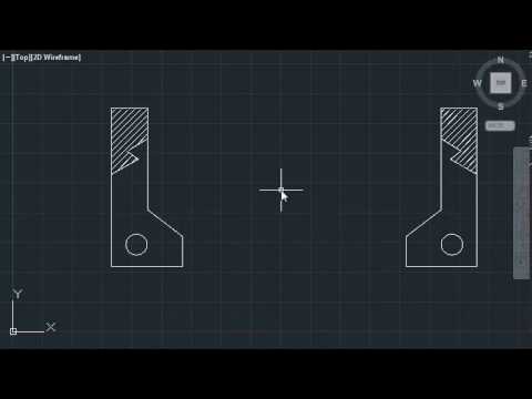
How to use MIRROR command tutorial in AutoCAD. Describe the steps required in using the mirror feature command mirror feature select feature continue select mirror plane in the box then select the back surface that you want mirror to be on why is it important to identify symmetrical features in designs. Select the mirror line.
Select sketch to be mirrored typically by clicking on it in the tree view. Pre-selected entities Copy link. In the Mirror dialog box click Select.
After you select some objects AutoCAD prompts you to select two points that define a line about which the objects will be mirrored. Select one or more sketch entities. Then go to features manager designtree and select your Cut Extrude 2 base pattern.
How to mirror geometry in SketchUp using Mirror. To begin use commands on the Sketch tab to create the geometry to mirror. The mirror feature command requires a point to mirror about.
In the Sketch toolbar. Use the Mirror tool in either of two ways. File - New - Part.
Then you have to select the direction reference which gives idea to tool to create array of patterns in x or y direction. Open SolidWorks CAD software.
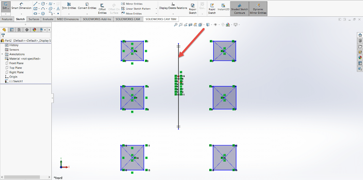
Solidworks Dynamic Mirror Entity Solidworks Dynamic Mirror Entity
How To Use Linear Pattern Sketch Tools In Solidworks Thinknext Technologies Private Limited Get Full Training Of S Sketching Tools Linear Pattern Solidworks

Mirror Sketch Geometry Inventor Autodesk Knowledge Network


0 Comments